Cars are expensive in Brazil, and sports cars even more so. When the VW Up was released here, starring the EA211 1.0 TSI engine with manual transmission, it quickly won the hearts of enthusiasts like myself. Small, lightweight, and surprisingly powerful, it can be tuned to extract even more performance. Still, it’s not a sports car. Unfortunately, Brazil never received the Up GTI that was sold in Europe.
In an attempt to make the Up feel sportier, and given that the instrument cluster is nearly identical to the Beetle’s, I decided to try installing the Beetle’s auxiliary gauges. Not only would they fit nicely, but they could also provide a more “enthusiast” feel without modifying the car’s wiring.
People have retrofitted these gauges on a VW Beetle by tapping directly into the instrument cluster CAN lines. I wasn’t confident this would work in a VW Up, and I didn’t want to risk cutting into the car’s cluster wiring. Instead, I aimed to make a plug-and-play solution.
I love to hack things, make them work where they shouldn’t, and understand how they work, so this was a perfect challenge.
Challenge 1: Reverse-Engineering the Gauges
The first hurdle was to understand how to control the gauges. These gauges are designed to listen to a CAN (Controller Area Network) bus—a robust vehicle bus standard that allows microcontrollers and devices to communicate with each other's applications without a host computer. In simple terms, various electronic modules in the car broadcast messages (called frames) onto a shared pair of wires. These two wires, known as CAN High (CAN-H) and CAN Low (CAN-L), use differential signaling. This means data is represented by the voltage difference between them, making the communication extremely reliable and resistant to electrical noise—a critical feature in a car's electrically harsh environment.
Since I didn't have a VW Beetle to "sniff" the original CAN bus messages, I had to reverse-engineer the protocol through research and experimentation. The process involved:
- Research: Scouring forums and VAG group documentation for common CAN frame IDs and data formats. Many VW/Audi parts share protocols, which was a huge advantage.
- Brute-force Experimentation: I powered the gauges on a bench and used an Arduino with a CAN transceiver to send different CAN frames until the gauges reacted. By sending a specific CAN ID and systematically changing the 8 data bytes, I could observe what made the needles for oil temperature and boost pressure move, or what controlled the clock and backlight.
Master CAN Frame Table
Here’s the complete list of CAN frames the gauges respond to:
| CAN ID | Byte 0 | Byte 1 | Byte 2 | Byte 3 | Byte 4 | Byte 5 | Byte 6 | Byte 7 | Description |
| 0x588 | - | - | - | - | Boost / 2 | - | - | Oil temp + 60 | Engine Oil & Boost |
| 0x62E | - | - | - | - | Hours × 0x10 | Minutes * 2¹ | - | - | Clock |
| 0x320 | 0xFF if engine is on, 0x0 otherwise | 0x01 if car is moving, 0x0 otherwise | - | - | Speed (km/h) | - | Adj. speed (+5%) | - | Driving Status / Speed |
| 0x470 | - | - | 0=auto, 1-100=% | - | - | - | - | - | Backlight Control |
¹ Plus 1 if the hour is 16:00 or later.
Challenge 2: Extracting Data from the Car via OBD-II
Unlike the auxiliary gauges, which passively listen for broadcast CAN frames, a car's OBD-II port works on a request-response basis. You can't just listen for oil temperature; you have to ask for it. This is done using the UDS (Unified Diagnostic Services) protocol.
Each OBD-II request is a CAN frame sent to a specific ECU (Electronic Control Unit) address. While often associated with the "Engine Control Unit," in this context, an ECU can be any module in the car, like the instrument cluster or the engine controller itself. The request asks for a piece of data identified by a DID (Data Identifier), and the ECU then replies with another CAN frame containing the information.
OBD-II Request & Response Deep Dive
The core of the logic is sending a UDS "Read Data by Identifier" request (service 0x22) and parsing the successful response. In the UDS protocol, a positive response is indicated by adding 0x40 to the original service ID, which is why the success code for service 0x22 is 0x62. Here is a detailed byte-by-byte breakdown of every request and its corresponding response.
UDS Request Frames
| Parameter | To ECU (ID) | Byte 0 (Len) | Byte 1 (Service) | Byte 2 (DID MSB) | Byte 3 (DID LSB) | Bytes 4-7 (Padding) |
| Current Time | 0x714 (Cluster) | 0x03 | 0x22 | 0x22 | 0x16 | 0x55 55 55 55 |
| Oil Temp | 0x7E0 (Engine) | 0x03 | 0x22 | 0x11 | 0xBD | 0x55 55 55 55 |
| Intake Pressure | 0x7E0 (Engine) | 0x03 | 0x22 | 0xF4 | 0x0B | 0x55 55 55 55 |
| Baro. Pressure | 0x7E0 (Engine) | 0x03 | 0x22 | 0xF4 | 0x33 | 0x55 55 55 55 |
| Vehicle Speed | 0x7E0 (Engine) | 0x03 | 0x22 | 0xF4 | 0x0D | 0x55 55 55 55 |
UDS Response Frames
| Parameter | From ECU (ID) | Byte 0 (Len) | Byte 1 (Service) | Byte 2 (DID Echo) | Byte 3 (DID Echo) | Byte 4 (Data) | Byte 5 (Data) | Bytes 6-7 |
| Current Time | 0x71C | 0x04 | 0x62 | 0x22 | 0x16 | Hour | Minute | Padding |
| Oil Temp | 0x7E8 | 0x04 | 0x62 | 0x11 | 0xBD | Temp MSB | Temp LSB | Padding |
| Intake Pressure | 0x7E8 | 0x03 | 0x62 | 0xF4 | 0x0B | Pressure (kPa) | - | Padding |
| Baro. Pressure | 0x7E8 | 0x03 | 0x62 | 0xF4 | 0x33 | Pressure (kPa) | - | Padding |
| Vehicle Speed | 0x7E8 | 0x03 | 0x62 | 0xF4 | 0x0D | Speed (km/h) | - | Padding |
Polling Strategy
Because requests must be sent one at a time, I implemented a polling state machine in the Arduino. This allows me to prioritize which data to fetch and how often:
- High Frequency: Intake pressure and vehicle speed are requested in rapid succession for real-time gauge updates.
- Medium Frequency: Oil temperature is polled every 5 seconds, as it changes slowly.
- Low Frequency: The clock time (every 30s) and barometric pressure (every 5min) are updated less often.
This trade-off keeps the gauges responsive without overwhelming the OBD-II bus.
Challenge 3: Making Everything Work Together and Mounting It in the Car
Once the electronics and code were working, the next challenge was integration and mounting. I wanted the gauges to look OEM and fit neatly in the dashboard.
The Electronics: An Arduino-Based Translator
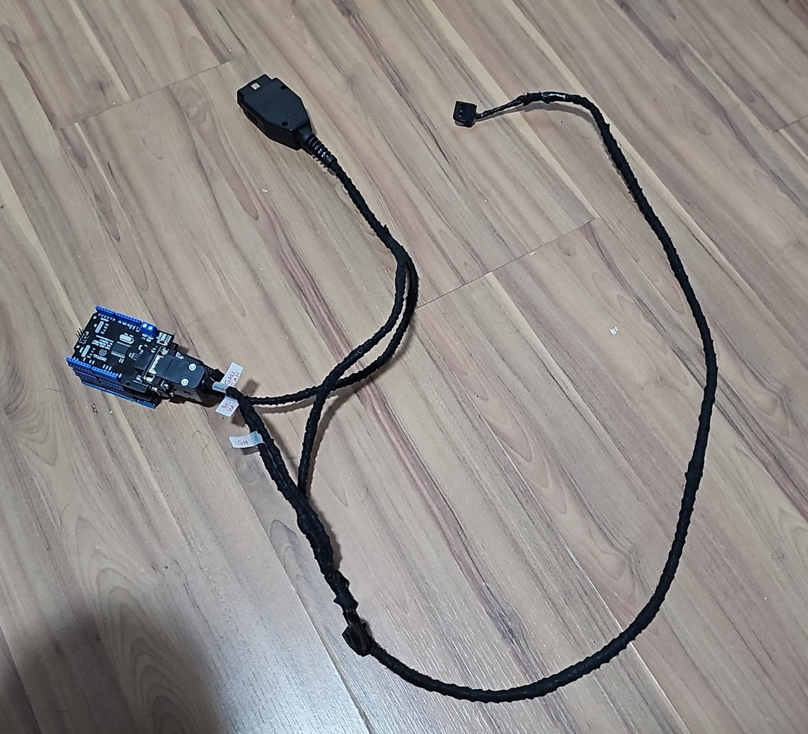
The brain of the operation is an Arduino Uno equipped with two MCP2515 CAN bus shields. All electronics are housed in a 3D printed enclosure.
Some might wonder why I chose an Arduino Uno over a more powerful (and compact) microcontroller like an ESP32. I initially started with an ESP32, but the Arduino Uno offered two significant practical advantages for this specific application. First, it can be powered directly by the car's 12V system through its onboard voltage regulator, eliminating the need for an external buck converter. Second, the shield form factor allows two MCP2515 CAN bus shields to be stacked neatly on top of the Arduino, creating a compact, self-contained unit with minimal wiring. This made for a much cleaner and more robust final installation.
- Shield 1 connects to the gauges’ CAN bus.
- Shield 2 connects to the car’s CAN bus via the OBD2 port.
- Arduino & Gauges are powered from the OBD2 port.
Here’s a diagram of how everything is connected:

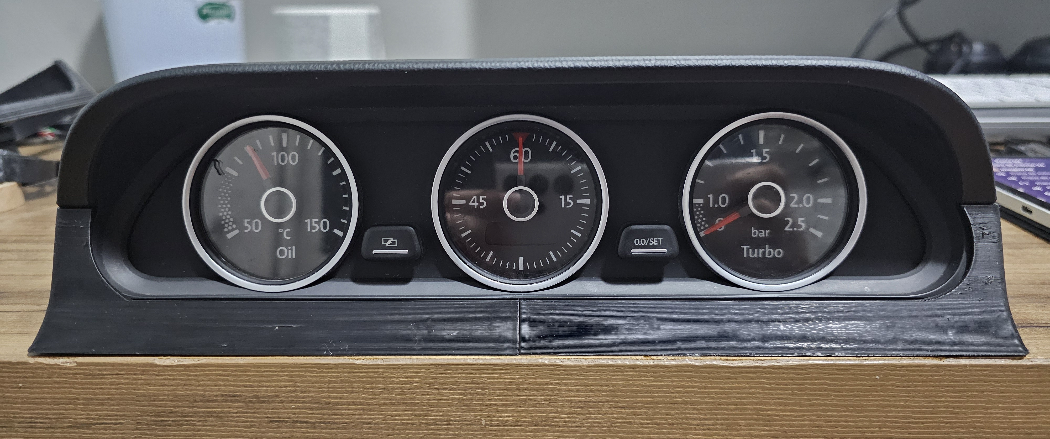
Mounting the Gauges
I designed a mount to fit where the factory phone holder normally sits:
- 3D design – modeled the mount to match the dashboard spot.
- 3D printing – printed in PETG (PLA would deform in Brazil’s heat; ABS is harder to print). The PETG part has been in my car for a year and held up perfectly.
- Finishing – glued, sanded, and painted for a clean look.
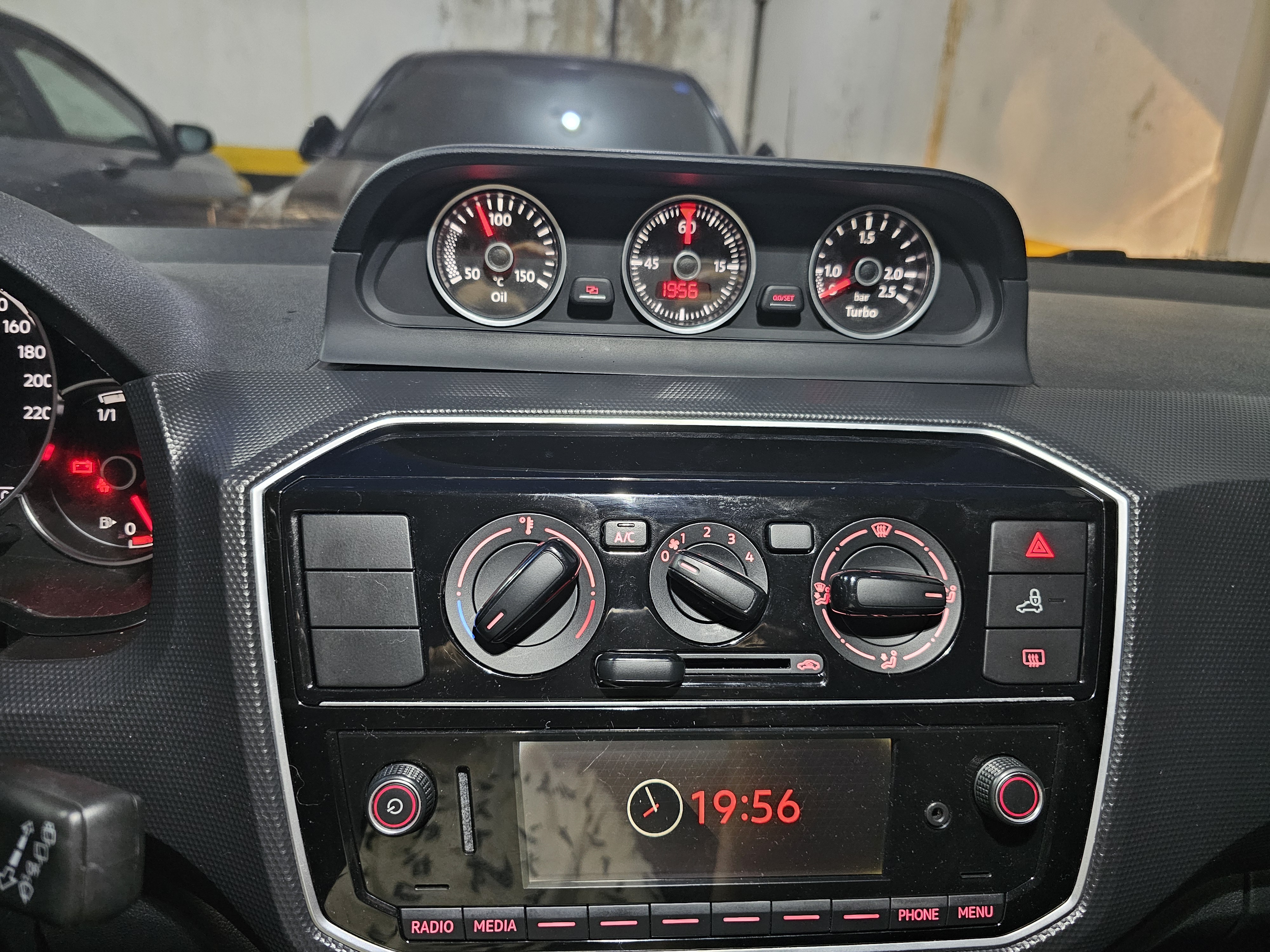
- Installation – screwed the mount into the dash in place of the original phone holder. The fit isn’t perfect yet, but it’s a solid start.
Potential Improvements
- Dynamic Backlight: Currently always on for simplicity. Could theoretically be synced with car lights.
- Efficient CAN Reading: Interrupts would be more efficient than constant polling, but the polling method works reliably.
Wrap-Up
This project combined reverse-engineering, embedded programming, CAN bus hacking, and 3D fabrication. It took patience and iteration to:
- Understand the gauges.
- Extract and prioritize data from the VW Up through OBD2.
- Integrate electronics and create a proper dashboard mount.The result? Fully functional Beetle auxiliary gauges working plug-and-play in a VW Up, with a custom mount and neat electronics tucked away.
Source Code
You can find the complete Arduino source code for this project on GitHub.